philuptagus
New Member
- Reaction score
- 0
Hi,
I have been asked to re-structure a small residential high school's network, due to the fact that the residents' (100+ students) bandwidth, at times, is slow, and the current network setup allows them to use (without permission) administration bandwidth and 'steal' IP addresses. Also, it compromises security. I must add this is a college preparatory high school and our students are talented and gifted, so their computing skills can test the most talented IT Professional.
To give you a better picture of the layout of the physical campus, there are two buildings separated by parking lot; one is the dorm and the other is where classes are held and the location of the administration building (approx. 40 staff with computers). Both buildings are wired for networking.
I was asked to start with the dorm, since this is where most issues are. Before I began, I was told our internet source is a T1. So let me give you a visual of what I saw when I went to the wire room:
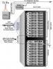
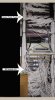
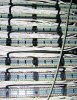
I located the "pipe" and from it were 12 optical cables (orange) leading to an optical box. When I opened the box, I could see (inside) all 12 optical lines connected to internal connectors. Now I closed the box with the knowledge that all 12 optical lines from the "pipe" are connected to 12 separate connectors inside the box. Looking outside the box I see 12 optical connectors (assuming 6 pairs, for RX/TX). The top two (pair) connectors on the box have an optical cable (orange) connected to a media converter (Allied Telesis ATFS201). [Let me add, for the record, that the next two (pair) connectors go to our phone system, an old PBX]. From the media converter there is a single RJ45 Cat5 cable connected to a switch (tier 2 port 21 to be exact). There are 10 of these switches, stacked and all are HP Procurve 2524 J4813A. These 10 switches are connected (100+ Cat5 cables) to the top rack which has 10 patch panels and they are all Sprint 449257 (manufactured in 1996 and are now discontinued). On the back-side of these patch panels are the "punch style" wire connections. So each cable is connected individually by the 8 wires within a Cat5 UTP cable (the RJ45 connecter is cut, exposing the 8 wires and connected to the back of these patch panels). So the Cat5 cables lead from the back of the patch panel, up several pipes to the dorm rooms.
Now that you have a picture of what I am facing, I have a question or two. The T1s I've encountered before had 24 wires. Have any of you seen our type of connection before (12 optical wires)? If I purchase more media converters, or a larger scaled one, can I utilize the remaining connectors from the optical box, create subnets (approx 4) by connecting the Cat5 cable (from the media converters) to routers and connecting a router per subnet (switched)? Also, I would like to factor in a server, preferably an SBS 2003 so I can manage the network. How would you all tackle this? Oh yes, other than re-crimping the jacks back on the existing Cat5 cables (from the dorm rooms that attach to the back of the patch panels) do any of you see any harm uninstalling (trashing) the patch panels and just using the switches? This would eliminate half the wiring (which, by the way, is a crazy mess). I'll work on the mess later.
Thank you all for your time and I look forward to reading your thoughts and ideas. Also, please refer to the attached network diagram I created.
I have been asked to re-structure a small residential high school's network, due to the fact that the residents' (100+ students) bandwidth, at times, is slow, and the current network setup allows them to use (without permission) administration bandwidth and 'steal' IP addresses. Also, it compromises security. I must add this is a college preparatory high school and our students are talented and gifted, so their computing skills can test the most talented IT Professional.
To give you a better picture of the layout of the physical campus, there are two buildings separated by parking lot; one is the dorm and the other is where classes are held and the location of the administration building (approx. 40 staff with computers). Both buildings are wired for networking.
I was asked to start with the dorm, since this is where most issues are. Before I began, I was told our internet source is a T1. So let me give you a visual of what I saw when I went to the wire room:
I located the "pipe" and from it were 12 optical cables (orange) leading to an optical box. When I opened the box, I could see (inside) all 12 optical lines connected to internal connectors. Now I closed the box with the knowledge that all 12 optical lines from the "pipe" are connected to 12 separate connectors inside the box. Looking outside the box I see 12 optical connectors (assuming 6 pairs, for RX/TX). The top two (pair) connectors on the box have an optical cable (orange) connected to a media converter (Allied Telesis ATFS201). [Let me add, for the record, that the next two (pair) connectors go to our phone system, an old PBX]. From the media converter there is a single RJ45 Cat5 cable connected to a switch (tier 2 port 21 to be exact). There are 10 of these switches, stacked and all are HP Procurve 2524 J4813A. These 10 switches are connected (100+ Cat5 cables) to the top rack which has 10 patch panels and they are all Sprint 449257 (manufactured in 1996 and are now discontinued). On the back-side of these patch panels are the "punch style" wire connections. So each cable is connected individually by the 8 wires within a Cat5 UTP cable (the RJ45 connecter is cut, exposing the 8 wires and connected to the back of these patch panels). So the Cat5 cables lead from the back of the patch panel, up several pipes to the dorm rooms.
Now that you have a picture of what I am facing, I have a question or two. The T1s I've encountered before had 24 wires. Have any of you seen our type of connection before (12 optical wires)? If I purchase more media converters, or a larger scaled one, can I utilize the remaining connectors from the optical box, create subnets (approx 4) by connecting the Cat5 cable (from the media converters) to routers and connecting a router per subnet (switched)? Also, I would like to factor in a server, preferably an SBS 2003 so I can manage the network. How would you all tackle this? Oh yes, other than re-crimping the jacks back on the existing Cat5 cables (from the dorm rooms that attach to the back of the patch panels) do any of you see any harm uninstalling (trashing) the patch panels and just using the switches? This would eliminate half the wiring (which, by the way, is a crazy mess). I'll work on the mess later.
Thank you all for your time and I look forward to reading your thoughts and ideas. Also, please refer to the attached network diagram I created.
Attachments
Last edited:
")
 Look forward to reading more info when you post it so we can try to help a little.