Help for understanding how the IC SC486 works.

alex777

Member
Reaction score
6
Location
Mexico
Hi, everyone!

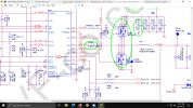
I'm having a video problem with my Sony Vaio VGN-C240FE... I've been 'scoping onto the motherboard power supplies, and I found that the +1.8 volts Mem. Pwr. Supply is not showing any signal on its power choke coil (PL5 on the schematic). Well, that signal comes from the IC SC486 (PU8), but I'm not quite sure where to test the in and out voltages, since it has 3 outputs and the input should be 12-13 pins VTTIN according to the datasheet, which differs with the schematic (12-13 pins +1.8 VOUT).

Could you please help me understand how this IC really works in order to give that +1.8 volts the memory needs to work?

Thanks in advance!
Alex.
 

Attachments

In what power state are you checking PL5? Remove power sources and check PL5 in diode mode to determine if you have a short or open. Plenty of small components on that circuit that could short that line. I'd make sure it's not shorted before investigating voltage signals. If you're sure it's not shorted then investigate mosfets PQ53 and PQ52.

If you want to get into board repair, check out Sorin's Electronics repair school YT channel: https://www.youtube.com/channel/UCooKQlg-HZ0PFAPc4Ymg3RA

He has a very active Discord channel but you might have to donate $5 through patreon to join. Lots of helpful board level techs in those channels, just read the rules before posting. They're real sticklers about their rules.

Something similar to what you're working with I think
 
Last edited:
In what power state are you checking PL5?
I 'scoped all power inductors from PL1 to PL10 with the motherboard working and the only one didn't show readings was the PL5.
Remove power sources and check PL5 in diode mode to determine if you have a short or open.
Sorry but I've never tested inductors before, buddy... how is the right procedure?
Plenty of small components on that circuit that could short that line. I'd make sure it's not shorted before investigating voltage signals. If you're sure it's not shorted then investigate mosfets PQ53 and PQ52.
I'll do that, so we can discard any short in that PL5 line like you say. I'll investigate those mosfets you mentioned on the schematic.
If you want to get into board repair, check out Sorin's Electronics repair school YT channel: https://www.youtube.com/channel/UCooKQlg-HZ0PFAPc4Ymg3RA
In fact I discovered that Sorin's channel a few days ago. Thanks!
He has a very active Discord channel but you might have to donate $5 through patreon to join. Lots of helpful board level techs in those channels, just read the rules before posting. They're real sticklers about their rules.
I'll keep that in mind.
Something similar to what you're working with I think
Thanks for the link!
 
Sorry but I've never tested inductors before, buddy... how is the right procedure?
I'm sure that @inbargains was speaking of a multimeter in 'Diode mode'. You need to become familiar with something more basic than an oscilloscope for first-checks.

Start watching Sorin's motherboard videos from the beginning, including his fault-finding tutorials – it will probably take you a couple of weeks. There's a lot of useful stuff in there, even if his methods can be quite rough sometimes, and most of his test methods just use a multimeter and a bench power supply (and Zippo fuel ... o_O ).

Personally, I found the Discord channel to be almost useless – too much of a jungle, and impossible to find anything later. I'm old and prefer a forum, but you might like it.
 
I'm sure that @inbargains was speaking of a multimeter in 'Diode mode'. You need to become familiar with something more basic than an oscilloscope for first-checks.
Yeah, I knew what he was speaking of, but I don't know how to interpretate those readings correctly. 😐
Start watching Sorin's motherboard videos from the beginning, including his fault-finding tutorials – it will probably take you a couple of weeks. There's a lot of useful stuff in there, even if his methods can be quite rough sometimes, and most of his test methods just use a multimeter and a bench power supply (and Zippo fuel ... o_O ).
I've been watching some Sorin's videos, and they help a lot, but I didn't watch that one you mentioned about the Zippo fuel method. o_O
Personally, I found the Discord channel to be almost useless – too much of a jungle, and impossible to find anything later. I'm old and prefer a forum, but you might like it.
I do prefer forums instead of paying some money on a Discord channel that I don't know if it's gonna help me or not.
 
I've been watching some Sorin's videos, and they help a lot, but I didn't watch that one you mentioned about the Zippo fuel method.
Lighter fuel features in many of them. Anyway, you need to view most of them, not just one or two. It isn't structured instruction, so you just have to follow along with the jobs he has on the bench at the time.

Regarding your present problem, inductors on a motherboard rarely fail, in my experience. By far the biggest source of faults is failure of a noise bypass capacitor – hundreds of those on a motherboard – and they usually fail short, bringing down a power rail (if they happen to fail open, it doesn't matter).

So essentially, especially given your symptoms, you're probably looking for a short from a power rail to ground. The meter in diode test mode is ideal for this; you'll probably need a bench power supply, too.

Theory of diode test mode: Fluke tutorial; StackExchange post, including a couple of links and some reasons why diode mode is useful.

Plenty more Google results and YouTube videos.
 
Diode mode (DM) injects voltage from your meter to the circuit and the readings represent the Voltage drop in that circuit. You put your meter in Diode testing mode, put your positive lead on ground and put your negative lead on the inductor or anywhere in that circuit. Active and correct circuits will measure 0.3 to 0.8 typically. A shorted circuit will measure 0 while an open circuit OL (over limit although most call it open line, same difference although technically incorrect).

Does the board power on? Some voltage rails only have power in certain power states. Your ram doesn't need power until the board is turned on, etc. Louis gives a good explanation of power states:

Do you have power on the 1.8v enable line? That rectifier only has power out if the enable lines are hot. I think you're chasing the wrong path frankly. If the laptop powers on, the BIOS is hot and running POST ops, if it doesn't get a signal from RAM because the rail is missing, it will give you beep codes like the memory is missing. Have you removed the memory and tried turning it on? Any difference?
 
Regarding your present problem, inductors on a motherboard rarely fail, in my experience.
Another technician told me that too.
By far the biggest source of faults is failure of a noise bypass capacitor – hundreds of those on a motherboard – and they usually fail short, bringing down a power rail (if they happen to fail open, it doesn't matter).
Probably the culprit is a bad capacitor, but I need to keep searching more information related to.
So essentially, especially given your symptoms, you're probably looking for a short from a power rail to ground. The meter in diode test mode is ideal for this; you'll probably need a bench power supply, too.
Power supply... I only have a Yihua 853D station which has 0-15V 1A. Maybe I'll have to acquire a power supply later on. Any suggestion for laptop and computer repairs?
Theory of diode test mode: Fluke tutorial; StackExchange post, including a couple of links and some reasons why diode mode is useful.

Plenty more Google results and YouTube videos.
Thank you very much for the links!
 
Diode mode (DM) injects voltage from your meter to the circuit and the readings represent the Voltage drop in that circuit. You put your meter in Diode testing mode, put your positive lead on ground and put your negative lead on the inductor or anywhere in that circuit. Active and correct circuits will measure 0.3 to 0.8 typically. A shorted circuit will measure 0 while an open circuit OL (over limit although most call it open line, same difference although technically incorrect).
Thanks for the technical information, buddy!
Does the board power on? Some voltage rails only have power in certain power states. Your ram doesn't need power until the board is turned on, etc.
Yes, the board turns on, and the fan spins normally, but I got no video on the LCD display.
Louis gives a good explanation of power states:
I'll check that out. Thanks!!!
Do you have power on the 1.8v enable line?
You mean on the PIN 1 of the IC SC486 (PU8)? I took a screenshot of it from the schematic so you can tell me if it is what you're referring to or not.
That rectifier only has power out if the enable lines are hot. I think you're chasing the wrong path frankly. If the laptop powers on, the BIOS is hot and running POST ops, if it doesn't get a signal from RAM because the rail is missing, it will give you beep codes like the memory is missing. Have you removed the memory and tried turning it on? Any difference?
I'm gonna remove the memory modules and see what happens.

Thanks for your help!
 

Attachments

  • Enable pin PU8.png
    Enable pin PU8.png
    184.8 KB · Views: 2
Yes that's the place to check but before you spend a lot more time chasing this, have you plugged in a VGA monitor to check if you have video on it? I'd probably back up and check the obvious first. Page 2 block diagram shows signal comes from North Bridge for both LVDS and CRT. Do you have signal on a CRT? SC486 seems more for charging the battery and powering ram in S3 power state (suspend mode).
 
Yes that's the place to check but before you spend a lot more time chasing this, have you plugged in a VGA monitor to check if you have video on it? I'd probably back up and check the obvious first. Page 2 block diagram shows signal comes from North Bridge for both LVDS and CRT. Do you have signal on a CRT?
Yes, I plugged in a VGA monitor and it doesn't show image at all.
SC486 seems more for charging the battery and powering ram in S3 power state (suspend mode).
That is what I was trying to check since the RAM has to do with video signals, right?

One thing I should mention... there's no CMOS battery in the laptop, so I can't tell if the VGA signals are working because the system might be "stuck" in the POST or setup screen, and since it's not getting to Windows, the system is not going to show any external video monitor.
 
Last edited:
Any suggestion for laptop and computer repairs?
@inbargains has more patience than me – everything he wrote is in links that I gave you. So is the answer to this question of yours, but a suitable linear (not switch-mode) bench power supply would be 0-30 Vdc, 0-3 A (an adjustable current limit is essential).

You must do the work yourself. Most of us are working techs and while we want to encourage you to get started and gain useful experience, don't expect to be spoon-fed the answers to everything (at least, not from me ;) ) as it takes a lot of time.

Start with these two Sorin's videos about laptop motherboards: part 1 and part 2.
 
One thing I should mention... there's no CMOS battery in the laptop, so I can't tell if the VGA signals are working because the system might be "stuck" in the POST or setup screen, and since it's not getting to Windows, the system is not going to show any external video monitor.
You have a gap in your understanding of POST (power on self test) sequence. The CMOS battery is only necessary to retain some user settings that are volatile in CMOS (settings that can be changed and stored). The battery isn't necessary for the BIOS to execute most POST instructions.

A laptop this old should have CRT signal without an OS. My gut says you have a NorthBridge problem. The bridge just used a heatsink and vulnerable to overheating if the laptop wasn't kept clean. On a 15 year old laptop it wouldn't surprise me to see it have issues. You're investing way more time than it's replacement value. Back in those days when these overheated, many just removed the CPU, heatsink, CMOS battery, any plastics, threw them in a 350 degree oven for 10 minutes, let them cool and hoped for the best. If still no video, replaced it.
 
@inbargains has more patience than me – everything he wrote is in links that I gave you. So is the answer to this question of yours, but a suitable linear (not switch-mode) bench power supply would be 0-30 Vdc, 0-3 A (an adjustable current limit is essential).

You must do the work yourself. Most of us are working techs and while we want to encourage you to get started and gain useful experience, don't expect to be spoon-fed the answers to everything (at least, not from me ;) ) as it takes a lot of time.

Start with these two Sorin's videos about laptop motherboards: part 1 and part 2.
Thanks for the links and your advice, man. :)
 
You have a gap in your understanding of POST (power on self test) sequence. The CMOS battery is only necessary to retain some user settings that are volatile in CMOS (settings that can be changed and stored). The battery isn't necessary for the BIOS to execute most POST instructions. A laptop this old should have CRT signal without an OS.
Yeah, I got confused about that... what I was going to say is that I didn't plugged in the HDD, but finally I did it and still no image on the VGA monitor.
My gut says you have a NorthBridge problem. The bridge just used a heatsink and vulnerable to overheating if the laptop wasn't kept clean. On a 15 year old laptop it wouldn't surprise me to see it have issues.
I just found a Shottky Diode (D8) broken close to the VGA connector (CN22), which is connected to number 12 pin of the CN22 (DDCDATA). I checked the number 2 pin of the Schottky (D8) and I have +5VDC, but since that diode is off the board (brushing the CN22 connector it popped out), I've got no output voltage in its pin number 1. Now, I checked the diode on forward bias and it's 0.286 volts, then on reversed bias, and it's OL, so I think the diode is OK. I've read that you need number 12 and 15 pins (DDCCLK) working in order to detect the VGA monitor. Is that right? 🤔
You're investing way more time than it's replacement value. Back in those days when these overheated, many just removed the CPU, heatsink, CMOS battery, any plastics, threw them in a 350 degree oven for 10 minutes, let them cool and hoped for the best. If still no video, replaced it.
I'm investing my time for learning purposes, since it's an old laptop and it's mine, so it's not a big deal screwing the things up little bit. ;)
 

Attachments

  • IMG_20210220_121144607.jpg
    IMG_20210220_121144607.jpg
    825 KB · Views: 1
Last edited:
Back
Top