NYJimbo
Well-Known Member
- Reaction score
- 2,010
- Location
- Long Island
Yes, it does..
Ok, if it DOES NOT get a tone when you are doing the test (screw to chassis) I mentioned before then there is likely to be a continuity problems.
Yes, it does..
Ok, if it DOES NOT get a tone when you are doing the test (screw to chassis) I mentioned before then there is likely to be a continuity problems.
It gets a tone when testing the screw to chassis as well. i Apologize for not mentioning this earlier.
Did you check for any fuses around the LCD connector to the motherboard ? LED based 1545's should have fuses around the connector. marked with F1 or similar. You can do a cont test end to end on the fuse to see if its still intact.

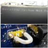
F4 looks like a 2amp littlefuse. Are you sure there are no other fuses around the LCD cable connector on the mobo ? If you are comfortable doing it you could bridge F4 to see if it works. Any fuse showing that its open like that is bad. Sometimes in rare cases the solder from the fuse to the mobo will break from heating and cooling and sometimes just reflowing both sides of the fuse will get it to work.
But if you can bridge it with solder or a tiny wire it should help you determine if that's the fault.
I would not just bridge it with solder permanently as it will not protect the motherboard in the future as it wont blow when it gets hot.

This is a Sony we're talking about. Look for F15 or F16. It's usually those fuses.
If you are not sure if you can do anything more then you might leave it as is if you think this bridge will hold. Many people will just bridge it and leave it. But the best thing to do will be to buy the correct fuse and put a new one in.
I know this is pretty tricky and you risk doing more damage the more you tinker with a solder joint so you are going to have to decide what to do next. Also be sure to cleanup any little solder or wire bits that might be floating around, they can end up elsewhere and cause more trouble.
Glad to hear this found/fixed the problem.
If I helped you can always click the little "reputation scale" in the upper right of any message. Thank you !
About grounds:
All grounds are the same, you always test ground by using MINUS pole of the DC jack as a reference. Most people is using ground shield of USB jack as a reference which is also good, as long as DJ jack connection is not loose. That ground that got disconnected is used to discharge static electricity that may happen when user touch laptop so instead of causing problems or restarts that charge gets under control.
You could also use multimeter and see if positive voltage is coming to the screen (those 2 red wires). That way you could find out right away that screen is not getting voltage
Hi Jimbo,
I dont agree with you.
So if thats correct what wires are used to supply LED inverter circuit?
As far as I remember these are the only wires used to supply LED inverter... inside is usually step-up DC converter and distribution chip that does both.
Its not like old CCFL inverters where 19V goes directly to the inverter.. and usually with separate cable.
Where they are? This is the only connector that goes to the LCD LED screen
Find that LVDS cable pinout and you will see.
We booth learn something new almost every day, today is your day
